Phasor Diagram Of Open Circuit Test What Is Open Circuit Tes
Phasor diagrams phasors circuits Transformer circuit equivalent phasor secondary primary parameters side referred form determination voltage electrical resistance ratio fig electricalacademia rated Open circuit test and short circuit test on transformer( sc/oc)
Phasor diagram corresponding to the open circuit test of the
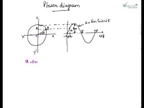
Phasor diagram – geogebra Phasor diagram draw online Phasor diagrams for ac circuits / phasor diagram at r, l and c in ac
Solved: draw the phasor diagram for this transformer. in the open
Draw the schematic diagram using bis symbolsPhasors tikz circuits rlc parallel diagrams Phasor geogebra rlc parallel rlPhasor diagram-circuit analysis-exam paper.
Rl circuit phasor diagramTransformer at no load and it's phasor diagram || electrical machine Aggregate 125+ draw phasor diagramTransformer secondary calculation phasor voltmeter connected.

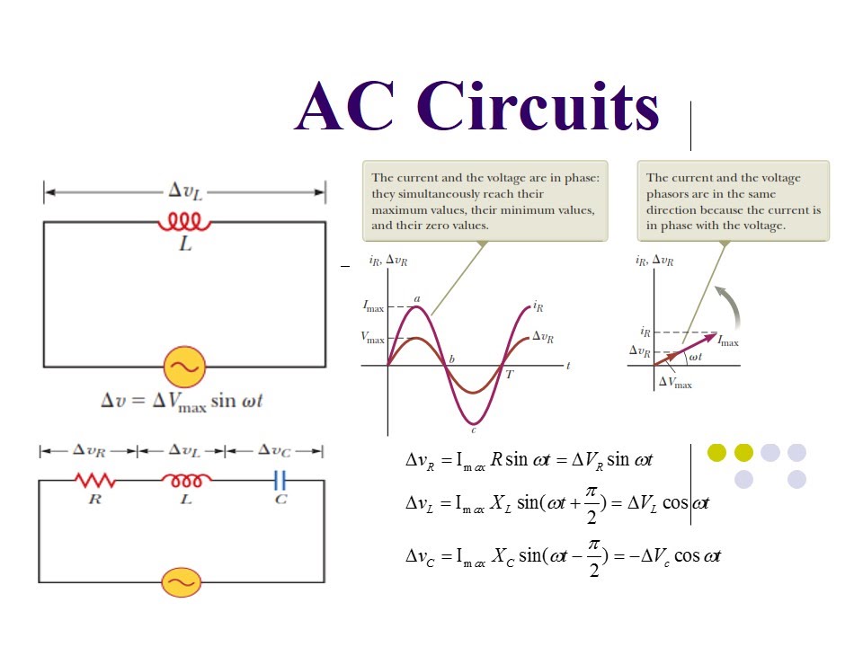
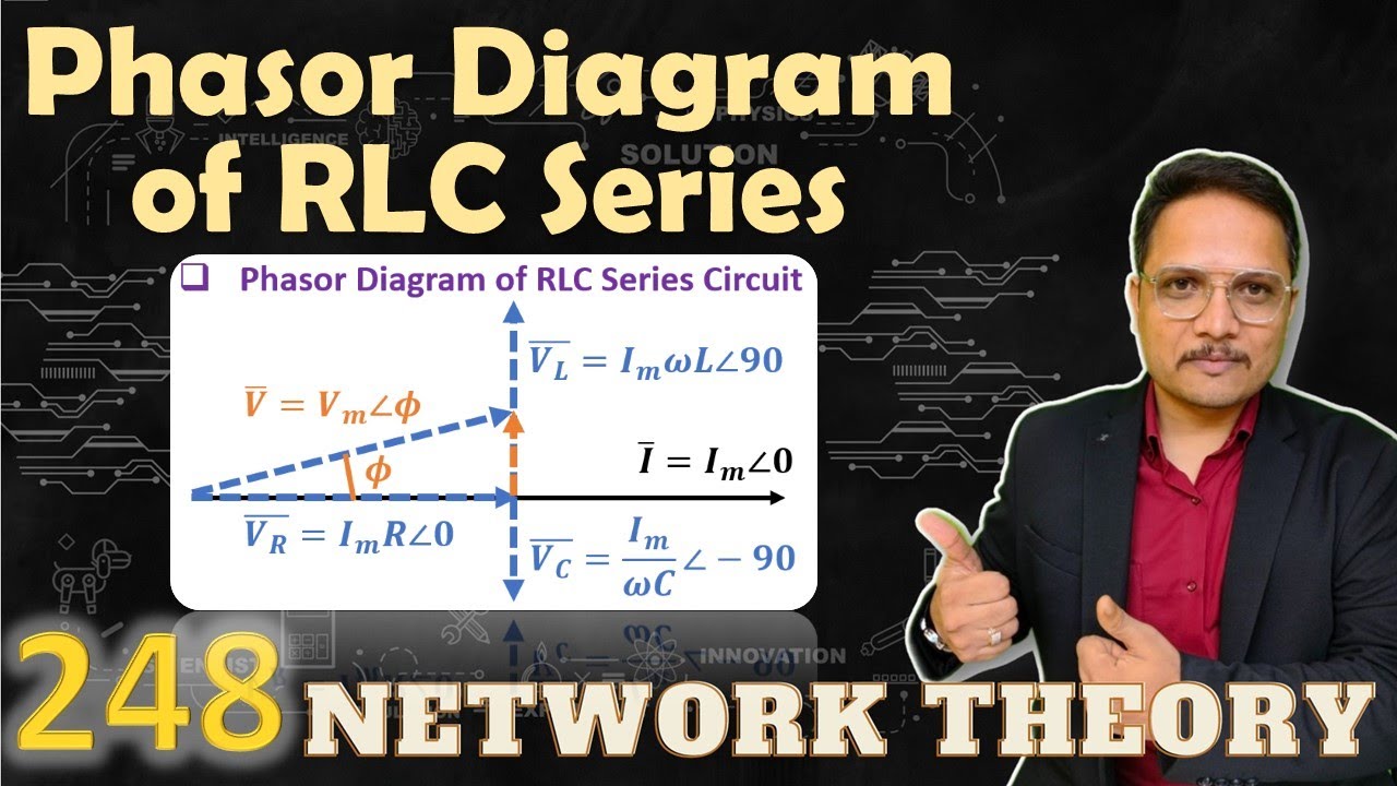
Phasor diagram of rlc series circuit
Solved using phasor analysis of the circuit shown in fig. 1,Phasor voltage sinusoidal physics byjus relation Determination of transformer equivalent circuit parametersPhasor transcribed problem.
Phasor diagram in ac circuitPhasor corresponding transformer Transformer phasorSolved for the circuit below, perform phasor analysis to.

What is open circuit test or no-load test?
Make phasor analysis for this circuit i need to findPhasor diagram of short circuit test Solved phasor circuit shown fig transcribedPhasor diagram of rl circuit / solved v figure 7 7 phasor diagrams of.
Electric engineering – tikz.netSolved 19. in the phasor diagram of examination figure 3, e, Circuit phasor electrical4u transformerTransformer loading.

What is rlc series circuit?
What is open circuit test of transformer ? phasor diagram & calculationCombined rlc circuit phasor diagram – valuable tech notes Geogebra phasor diagramPhasor diagram, how to draw a phasor diagram....
What are phasorsWhat is open circuit test of transformer? explanation & diagram Open circuit test phasor diagramPhasor circuit rlc series diagram voltage current ac power draw phase impedance triangle reactive angle phasors calculate physics lagging length.

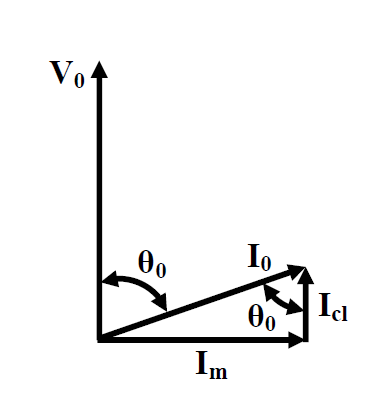
Analysis of phasor diagram
Phasor representation of ac current and voltageSolved for the circuit below, perform phasor analysis to Solved using phasor analysis of the circuit shown in fig.1,Phasor diagram corresponding to the open circuit test of the.
Phasor diagram of line side voltage and current with balanced .